
Goddard Space Flight Center
Radiation Effects Facility (GSFC REF)
Providing TID Services Since 1998
This Webpage Last Updated: January 28, 2021
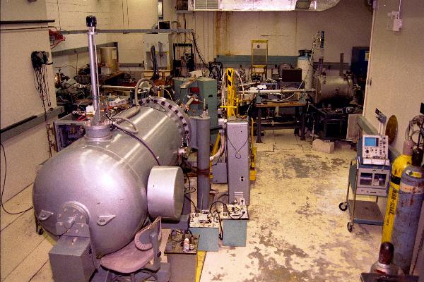
Damage Van de Graaff, Steering Magnet and Test Chamber.
Radiation Sources:
Gamma Source: Two separate irradiators available; a low intensity large area source suitable for low intensity and very low intensity studies (ELDRS); and a medium intensity irradiator for typical NASA orbit/missions.
- Particle Accelerators: Two 2 MeV Van de Graaff (one for damage testing and one for instrument calibration) and a 150 keV Potential Drop (instrument calibration).
Applications:
Radiation damage testing of spacecraft electronics, solar cells and microcircuits; optical sensors, couplings, coatings, lenses and filters; spacecraft paints, coatings, blankets and structural materials;
- Calibration and development of magnetospheric and inter planetary particle sensors, low energy X-ray and other radiation measuring instruments.
Availability:
The Facility is available to NASA Centers, other Government Agencies, Contractors, Universities and Manufacturers, on an as-available basis.
Host Location:
GSFC, Greenbelt, MD, Owned by NASA, Operated by SSAI, Inc.
Contacts for Costs and Scheduling:
Gamma, Martin Carts, 301.286.2600, martin.a.carts@nasa.gov
GSFC Radiation Effects Database:
A complete list of all electronic components tested at Goddard (microcircuits, transistors, diodes, etc.) for TID and SEU/SEL is available through the OFA Library and the WWW on the Radiation Effects and Analysis Home Page at GSFC.
- Copies of TID reports are available on request from the OFA Library by calling 301-286-7260. TID reports are in the process of being put on the web.
- All SEU/SEL reports on parts tested by GSFC are also available from the Radiation Effects and Analysis Home Page. http://radhome.gsfc.nasa.gov
Gamma Ray Source:
The sources are contained in a 20’x20’ shielded room with a viewing window. The high ceiling and raised floor of the room ensure very low back scattering (i.e. low secondary radiation).
- The current source provides dose rates from 3 krads/min to 0.01 Rads/min depending upon the size-volume of the boards and the distance from the source.
- Experiments can be placed at any location in the room. This includes individual parts on a board, complete instruments and even an entire spacecraft on demand. Many different test boards can be irradiated simultaneously at the required dose rates within the available range.
- The dose rate uniformity is within ±
10% over a typical test board of 9" x 12".
- The dose rate is measured in real-time by ion chamber monitors.
- The facility has been actively used for low dose rate Total Ionizing Dose (TID) testing of electronic devices for the last 30 years.
- Recent evaluations include ADCs, DACs, OpAmps, DC\DC converters, V/f converters, Voltage References and Regulators,Power MOSFETs, and high-density memories for MIDEX, GOES and IRAC., SMEX, HST, JWST, SWIFT, LRO, SDO.
- In-situ characterization of components is possible.
- Costs and schedules are worked out on an individual project basis. Depending on schedule and method of funding, lead-time can be as short as one day. Non-NASA groups writing purchase requests through GSFC need a lead-time of 2 to 3 months. Contracting through the support contractor Unisys is faster for non-NASA groups.
2 MeV Damage Study Accelerator:
A Van de Graaff particle accelerator capable of providing beams of either protons or electrons with an energy range from 100 keV to 1.7 MeV in vacuum with a beam intensity range of 100m
A to 0.001m
A.
- Protons are available in a beam spot up to 2" diameter in the 2 ft diam. by 2 ft long vacuum chamber.
- Electrons are available, in vacuum, in the same chamber, spread to a 10“ diam. spot. Electrons are also available in air, through a 2” diam. window.
- Numerous customizable beam ports are available, including vacuum test chambers.
- The primary vacuum test chamber for housing devices under test has dimensions 23"D x 23"L. The test chamber can be pumped down to 1x10⁻⁶ Torr using a turbo pump.
- The particle fluence (dose rate) is measured with a Faraday cup or solid state detector.
- The special features include fine control of beam energies and intensities throughout the range for appropriate simulation of particle radiation damage effects in the planetary magnetospheric environment.
- Primarily used to simulate the solar wind for the evaluation of optical components, spacecraft coatings, paints, structural materials and solar cells. It is also used to investigate the recombination of primary chemistry in ices of comets, ice moons and interstellar particles.
- Recent irradiations were done for programs such as Code 691 (Cosmic Ice), LRO-LOLA Instrument and JPL-JUNO, Electro-Static Discharge in electrical cables used outside the space craft.
2 MeV and 120 keV Instrument Calibration Accelerators:
Both accelerators provide beams of H, He, C, N, O, Ne, Ar, Kr, and Xe ions.
- The 2 MeV accelerator provides electron, and ion beams with energies from 35 keV to 1.7 MeV with beam intensity in the range of 1m
A to 10-9 m
A/cm2.
- The 120 keV accelerator provides electron and ion beams with energies from 1 keV to 120 keV with beam intensity in the range of 1m
A to 10-9 mA/cm2.
- Both accelerators are used for test and calibration of spacecraft particle detectors as well as interference and damage testing of other types of spacecraft instruments.
- The beam diameter is defined by aperture, from 0.020" to 0.5" in 9 steps or 2" without an aperture.
- Three test chambers, 19.5"L x 19.5"W x 23"H, 17"Diam x 30"H, and 30"Diam x 38"H (the last one can be borrowed from APL) are available for housing the detector/instrument for calibration. All the test chambers have a baseline pressure of approximately 5x10⁻⁷ Torr using cryogenic pumps.
- Integrating electrometers are used for charge collection and measuring total ionizing dose. The available electrometers are Elcor Model A310B and A310C, Tomlinson Research Model 2000AEC, and Keithley models 617, 610B, 610C.
- Solid State Detectors, Pulse Counters and Pulse Height Analyzers are used for measuring particle rates and energies. Several HP 6201L scalar timers, two Nuclear Data Model 62 and two Canberra 35+ multi-channel analyzers are available.
- Special features include the fine control of beam energies and low beam intensities for the development, test and calibration of spacecraft scanners and sensors.
- Recent evaluations include instruments for CASSINI, CLUSTER and EOS IMAGE.
Test Chambers Available for Instrument Calibration:
The 20" x 20" Chamber:
- The chamber sits on a base plate and is either 9.75", 19.5" or 22" high depending on how many sections are stacked up.
- The chamber is Helium Cryro-Pumped. Pressure typically reaches 9x10⁻⁶ torr, with an Instrument, after 1 hr, dropping to 2x10⁻⁶, after several hrs, depending on instrument out-gassing, and may bottom out at 5x10⁻⁷ overnight.
- The beam enters 4.75" above the base plate through a 2" I.D. port, but typically apertures outside the chamber limit the beam from 0.5" to 0.020" in 9 steps.
- The beam monitor, usually solid state, is mounted just inside the entrance port on a remotely movable arm, and is positioned directly in the beam or completely out.
- Instruments sit on a 1/4" thick 6" diameter turntable, mounted on a 3/4" vertical shaft coming up through the base plate. The shaft/turntable can be raised up and down manually, and can be manually or computer scanned in steps repeatable to 0.2°
+ 0.1°.
- The chamber is rectangular with seven 2" I.D. ports available to mount flanges with feed thru's.
- There are two flanges with 4 BNC’s on each flange, two flanges with 4 SHV's on each flange (up to 9KV).
- We have 2 cables, approx. one foot long inside the chamber and one foot outside. Each cable has 55 wires, ending in 50 pin cannon connectors (the extra 5 wires are free), DDM 50P outside the chamber and DDM 50S (female) inside. Any of these can be moved to different port locations around the walls of the rectangular chamber.
- There are some spare standard NIM Bin Bias Supplies, Amps and Thresholds etc. available for out-of-town groups to use.
The 17" diameter by 30" high chamber:
- The chamber is Helium Cryro-Pumped. Pressure is 9x10⁻⁶ torr, with an Instrument, after 1hr, dropping to 2x10⁻⁶, after several hrs, depending on instrument out-gassing, and may bottom out at 5x10⁻⁷ overnight.
- The beam enters the chamber 7.1" above the turntable, perpendicular to the centerline of the cylinder, and there is another 23" of free space above the beam. Aperatures outside the chamber limit the beam diameter to .625", .1", .050".
- The beam monitor, usually solid state, is mounted just inside the entrance port on a remotely movable arm, and is positioned directly in the beam or completely out.
- Instruments sit on the 17" diam. Turntable and must be spaced up and down with shims or slotted feet. The turntable is remotely manually adjustable 360 degrees + .1
- There are three 2" ID ports, above the beam line, which can used with all the other feedthrus mentioned in the above description of the 19.5"x 19.5" chamber.
Test Chamber Cleanliness:
The chambers are pumped down and sustained by non-oil cryogenic vacuum systems. Contamination from uncured epoxy, silicone, machine oil, etc. can kill flight detectors. Please do not plan to use our chambers to out gas a prototype or flight unit immediately after it has been soldered or glued.
Other Possible Uses of the Chambers:
With some set up the test chambers could also be used for:
- Simulation of the magnetospheric environment in thermal vacuum;
- Vacuum, steady state stability soak for contamination;
- Simulation of rapid pressure changes during launch;
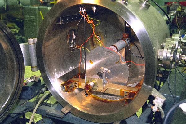
Damage Van de Graaff Test Chamber.
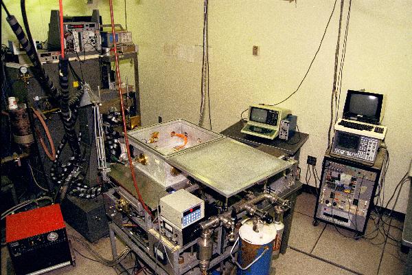
150 keV Accelerator, Steering Magnet, 20" x 20" Test Chamber,
Pumping Station and Turntable Controls.
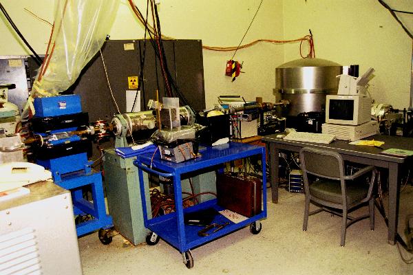
Steering Magnet, Electrostatic Focus and 30" diameter x 38" high
Test Chamber for the Instrument Van de Graaff.
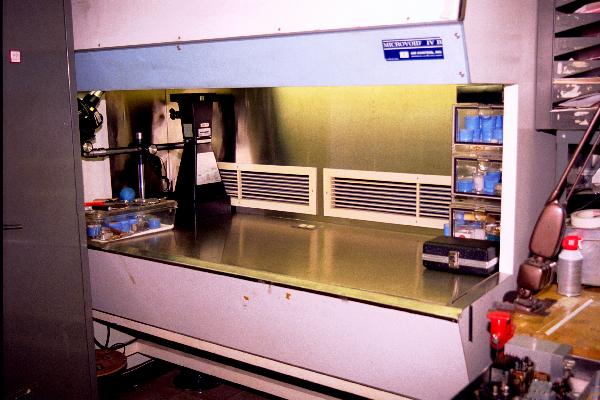
Clean Bench Assembly Area
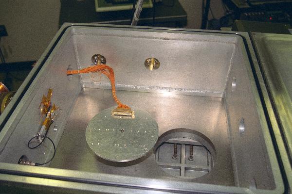
20" x 20" Test Chamber, showing Beam Monitor,
Turntable, 2" Ports and 50-pin Cable.
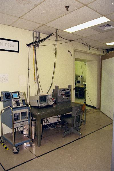
Data Reduction and Ground Station Area, for the Instrument Van de Graaff,
showing space available, Cable Penetrations through wall, and peripherals.
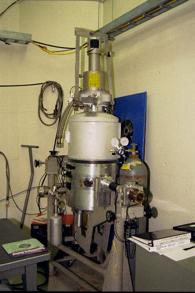
17" x 30" Test Chamber for Instrument Van de Graaff.


